Battery Management System
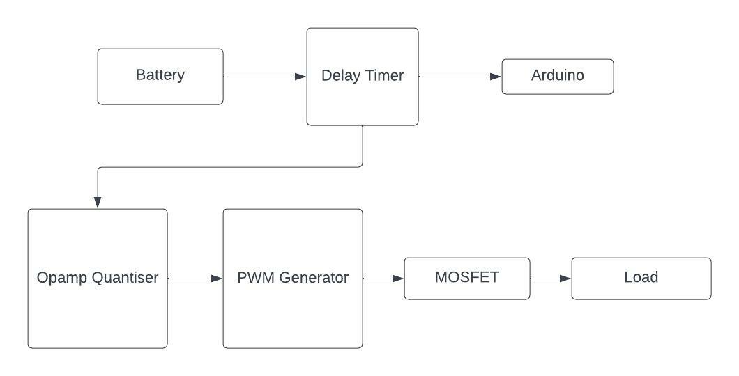
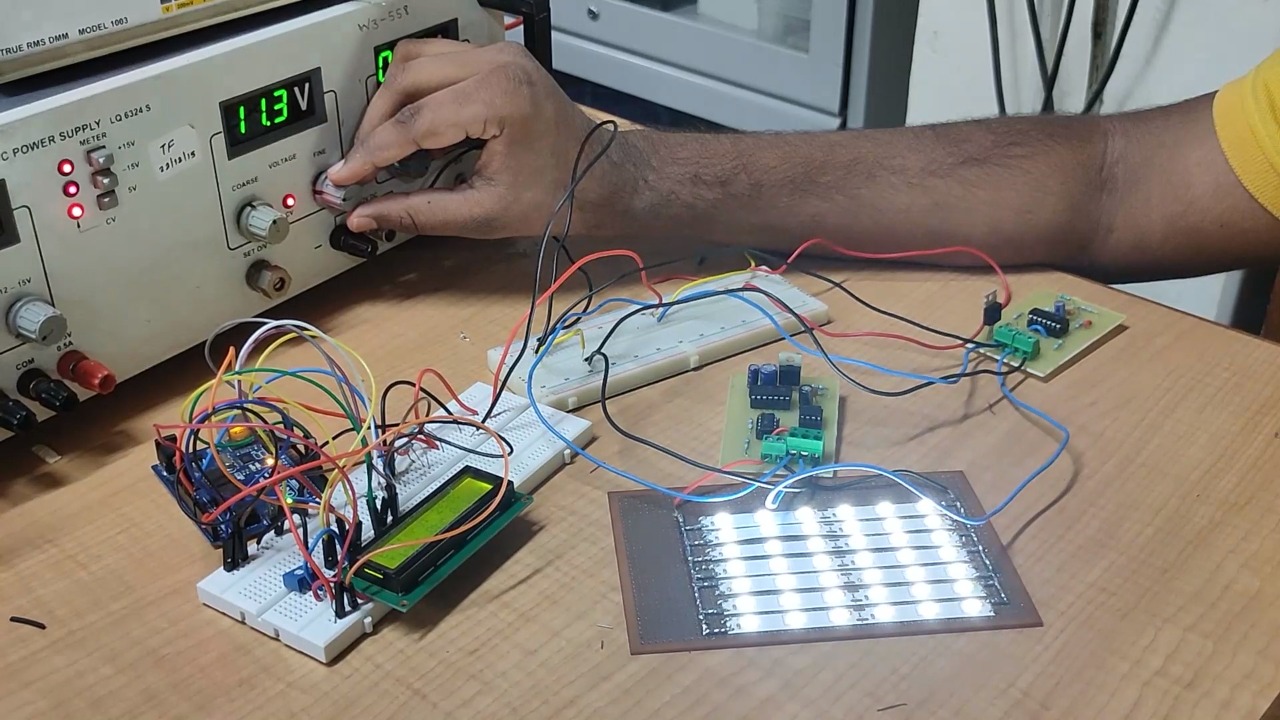
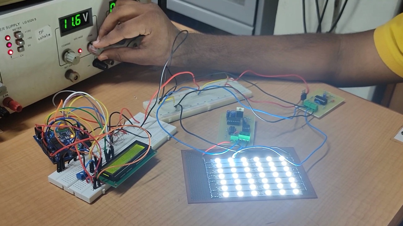
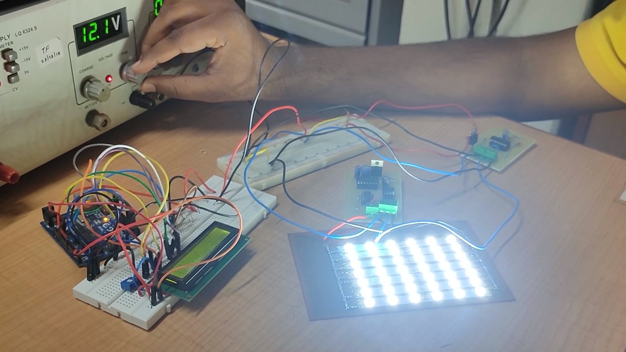
Variable output according to state of charge of battery Solar-powered street lights are being deployed across India. With the increasing use of such street lights, we reduce our dependence on conventional energy. Unfortunately, most of them break down within a year or so. The two key factors are poor battery management and load control. Thus to extend the lifetime of the devices we need to have better battery management. The design objective of the project is We have implemented this circuit using basic electronic components to make it cost-effective. Each subsystem can be used as a separate circuit if required. The system comprises of four subsystems: Arduino is used for displaying the State of Charge (SoC) of the battery. The results indicate that this circuit is a successful and cost-effective way of solving the problem and making the street lights more durable. The job of Delay Timer subsystem is to turn off the circuit for 5 minutes and then turn it back on. This was done for proper measurement of state of charge of the battery. This subsystem was implemented using monostable multivibrator using 555 timer IC, and a simple RC circuit. The comparator quantizes the incoming battery voltage level to three voltage levels which then vary the duty cycle of PWM circuit. To discretize the voltage levels we have implemented 4 comparators using LM 324 IC. The fact that opamp is comparator is used to develop this circuit. According to the input voltage, the PWM generator outputs a PWM signal that is used to control the gate pin of MOSFET subsystem. The generated signal is the one that directly controls the output of the full system. The output of the PWM circuit is applied at the gate of a power MOSFET. As the duty cycle of PWM is changed, the mean voltage appearing at the gate terminal changes and thus we change the current flowing through the MOSFET and by varying the current the intensity of the LED (output system) changes. In order to quickly test the circuit, a power supply was used instead of the battery. Our assumption was that the battery always remained between 11V (0%) and 12.6V (100%). All of the subsystems were implemented on a PCB and were working as expected. The results at voltages 11.3V (output at 25%), 11.6V (output at 50%) and 12.1V (output at 100%) are as follows. The presented circuit solves the above mentioned problem. It achieves all the objectives that were mentioned and is cost-effective. This project was made by Shubham Ojha (me), Apoorva Hotkar and Aditya Anavkar. I would like to express my gratitude to Prof. Joseph John for providing support and guidance.Aim
Implementation
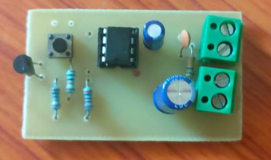
Delay Timer
Opamp quantiser
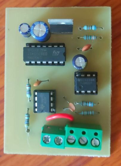
PWM Generator
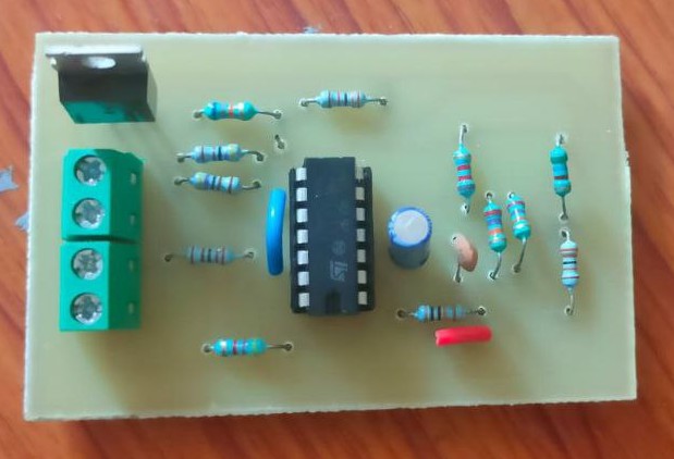
MOSFET subsystem
Results
Conclusion
Acknowledgements
References